The final gates I'll examine are the XOR and XNOR gates.
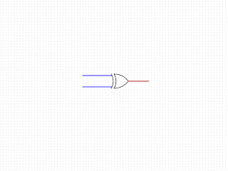 |
XOR
|

|
XNOR
|
To explain these gates, I'm going into the real world away from computers.
Most of us understand that the lightswitch at the bottom of the stairs can control the upstairs light, and the upstairs switch also does the same. This is an example of an exclusive OR system. When both switches are in the up position (off), the light is off, but as soon as one of them gets selected to down (on), the light comes on. When the other switch gets put to on, making them both on, the light goes off. When one of those switches then gets turned off, the light comes on again. We know that the light is on only, or exclusively, when one switch is on, but not both.
I'm not adding a component schematic for these gates as they are very quickly built from NAND gates which I already have a schematic for. Here is an XOR built from NAND gates showing each state of the truth table. Dark green lines indicate a low voltage, or FALSE and light green lines indicate a high voltage or TRUE
 |
Both inputs FALSE, output FALSE
|
A and B both FALSE, the left NAND gate produces a TRUE output (as seen in the NAND explanation). This gives one TRUE input to both the top and bottom middle gates along with the FALSE directly from A and B. Again, from the NAND explanation, this means the outputs from both middle gates are TRUE inputs to the final gate. This means that gate outputs FALSE.
 |
Input A=TRUE, B=FALSE, output TRUE
|
A TRUE and B FALSE, the left NAND gate now has 1 TRUE input and 1 FALSE. This doesn't affect it's output. As the middle top gate now has 2 TRUE inputs, it gives a FALSE output to the final gate. The bottom middle gate still gives a TRUE output to the final gate. As this is NAND, it gives a TRUE output.
 |
Input A=FALSE, B=TRUE, output TRUE
|
A FALSE and TRUE, the same as above, but it's the bottom of the middle gates which now outputs TRUE and the top one FALSE. Again, the final gate gets 1 TRUE and 1 FALSE, meaning it's output is TRUE.
 |
Input A=TRUE, B=TRUE, output FALSE
|
Finally, A and B are both TRUE. This switches the output of the left gate to FALSE giving both middle gates 1 FALSE input and 1 TRUE. As these are NAND, this means their output is TRUE. That gives the final gate 2 TRUE inputs, meaning it's output is FALSE.
Truth tables for these two gates:


Comments
Post a Comment