The AND gate
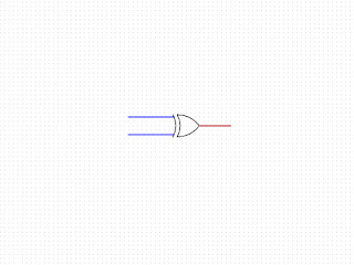
The next logic gate is the AND gate, the symbol for which is:

I've shown a 2 input AND gate, but you can have as many inputs as you choose to build into your circuit. This logic circuit is useful when we only want an output when input A AND input B are a logical 1 or TRUE.
Where could this apply? Suppose you're tasked with building a system for silent voting. Every person voting must vote yes for the vote to pass, and you don't have the option of just watching the hands being raised. I understand that sounds a little contrived, but if voting is being done remotely, this could occur.
One way of building a 2 input AND gate from discrete components is below, if further inputs are required, more transistors need to be added in the same fashion:

As you can see, when inputs A AND B are off or logical FALSE, there is no voltage applied to the bases (labelled 3) on the transistors. This means the transistors are not conducting from collector (labelled 2) to emitter (labelled 1) so the output is 0 or logical FALSE.
If A is on and B off, the voltage at the base of the transistor (3) turns it on and it conducts from the collector (2) to the emitter (1), but current cannot flow through transistor B, so the output is still 0/FALSE. The same is true if B is on and A off, current cannot flow through to the output.
It is only when A and B are on making the transistors conduct from their respective collectors to emitters that current can flow through the circuit to give a potential difference between the top of the resistor and ground which gives a logical TRUE, or on.
Please note that the reason for the pins on the transistors being labelled with numbers rather than letters is that I'm using kicad schematic capture for these diagrams. As this software is designed for designing circuits, the numbers represent actual component pins rather than what the pins are connected to inside the device.
Truth table for this gate
| A | B | Output |
| 0 | 0 | 0 |
| 0 | 1 | 0 |
| 1 | 0 | 0 |
| 1 | 1 | 1 |

Comments
Post a Comment