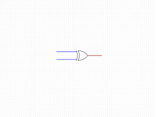
The OR gate
The next gate is the OR gate.

The purpose of this gate is to produce a logical TRUE if any of the inputs are TRUE. An example of it's use could be to light an "occupied" sign outside a changing room if any of the cubicles have someone in them. This would be useful if the staff member responsible for cleaning is not the same gender as the users.
This gate will be used to construct further logic circuits, but the example above is given to show that it can be used outside purely digital logic.
A way of constructing this gate using transistors is below, but of note is that it can be constructed quite simply using diodes. I've used transistors for this to follow the same pattern as in previous gates

When both A and B are off, both transistors are switched off allowing no current to flow, giving a logical FALSE at the output.
If A is on, the top transistor will be switched on allowing current to flow from VCC to the output giving a logical TRUE. This is independent of whether B is on or not.
The reverse is also true; when B is on, the bottom transistor is switched on and current will flow giving TRUE independent of A.
The truth table for this gate.
| A | B | Output |
| 0 | 0 | 0 |
| 0 | 1 | 1 |
| 1 | 0 | 1 |
| 1 | 1 | 1 |

Comments
Post a Comment