The half-adder circuit
The half adder circuit.
To construct an ALU, we need circuits to do the arithmetic and logic. The first building block I'm going to put in my ALU is the half-adder circuit. This comprises of a 2-input AND gate and an XOR gate. Thinking back to the circuits for these, there are 2 transistors in each AND gate and 3 in each NAND gate. Given that the XOR is made of 4 NAND gates, that comes to 14 transistors. Making a drawing of this as components would take a lot of time, and it's only part of a single function (adding two binary numbers) within the ALU, so we abstract it to as few logic symbols as we can.
Before explaining the circuit, I need to point out how addition in binary works. Humans work in base 10, and some early general-purpose computers were built to work this way, but it is far more efficient in terms of component count and circuit complexity to build and work in binary. Notable examples of these, according to what I could find online, include ENIAC, the Harvard Mark 1, the IBM 650 and the UNIVAC computers.
Binary numbers are written (typed and displayed) with the least significant bit on the right in exactly the same way as decimal numbers are. The difference between the systems is that in decimal, we have ten variations at each position before rolling over one digit to the left, giving us units, tens, hundreds, thousands and so on multiplying each position by 10 to get the next.. In binary, there are only two possible variations at each position, so we have units, twos, fours, eights, sixteens, thirty-twos and so on multiplying by 2 to get the next position.
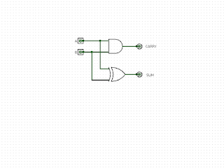
When adding 2 binary digits, known as bits, in the circuit. The output of the XOR gate gives the sum of the inputs and the output of the AND gate is a carry into the next column.
When A is 1 and B is 0, the sum outputs 1 and the carry outputs 0.
When A is 0 and B is 1, the sum gate outputs 1 and the carry outputs 0, again.
When both A and B are 1, the sum outputs a 0 and the carry a 1.
When both inputs are 0, the output of both gates is 0, which is shown in the first diagram.
A lot of people used to disparage computers as just glorified pocket calculators, with those who liked playing them (myself included before I learned much more) disagreeing, but the reality is that a general purpose computer really is just a glorified pocket calculator, and with the advent of the smartphone, we've got very powerful general purpose computers in our pockets. Granted, it can do so much more than those old pocket calculators, but the innards of the processor contain many of the same circuits.
The brain of a computer is the processor, nowadays built all on one chip, but once built of many discrete components, and the heart of that is the Arithmetic and Logic Unit, or ALU.
To construct an ALU, we need circuits to do the arithmetic and logic. The first building block I'm going to put in my ALU is the half-adder circuit. This comprises of a 2-input AND gate and an XOR gate. Thinking back to the circuits for these, there are 2 transistors in each AND gate and 3 in each NAND gate. Given that the XOR is made of 4 NAND gates, that comes to 14 transistors. Making a drawing of this as components would take a lot of time, and it's only part of a single function (adding two binary numbers) within the ALU, so we abstract it to as few logic symbols as we can.
Before explaining the circuit, I need to point out how addition in binary works. Humans work in base 10, and some early general-purpose computers were built to work this way, but it is far more efficient in terms of component count and circuit complexity to build and work in binary. Notable examples of these, according to what I could find online, include ENIAC, the Harvard Mark 1, the IBM 650 and the UNIVAC computers.
Binary numbers are written (typed and displayed) with the least significant bit on the right in exactly the same way as decimal numbers are. The difference between the systems is that in decimal, we have ten variations at each position before rolling over one digit to the left, giving us units, tens, hundreds, thousands and so on multiplying each position by 10 to get the next.. In binary, there are only two possible variations at each position, so we have units, twos, fours, eights, sixteens, thirty-twos and so on multiplying by 2 to get the next position.
When adding in decimal, we can hold up to ten values in the units column, 0 through to 9. When adding in binary, we can only hold 2 values, 0 to 1.
Consider this sum in decimal, 5 plus 5. Intuitively (due to repetitive learning), we know this is 10, or 0 in the units column and a digit carried into the tens.
In binary, we do the exact same thing, but instead of getting to 10 before we carry a digit into the next column, we can only get to 2. Using transistors to build a half-adder (and the full adder which comes after) makes addition in binary very simple.
The half-adder circuit:

When adding 2 binary digits, known as bits, in the circuit. The output of the XOR gate gives the sum of the inputs and the output of the AND gate is a carry into the next column.
 |
| A=1, B=0 |
When A is 1 and B is 0, the sum outputs 1 and the carry outputs 0.
 |
| A=0, B=1 |
When A is 0 and B is 1, the sum gate outputs 1 and the carry outputs 0, again.
 |
| A=1, B=1 |
When both A and B are 1, the sum outputs a 0 and the carry a 1.
When both inputs are 0, the output of both gates is 0, which is shown in the first diagram.
The truth table for this circuit is below.
| A | B | sum | carry |
| 0 | 0 | 0 | 0 |
| 0 | 1 | 1 | 0 |
| 1 | 0 | 1 | 0 |
| 1 | 1 | 0 | 1 |

Comments
Post a Comment