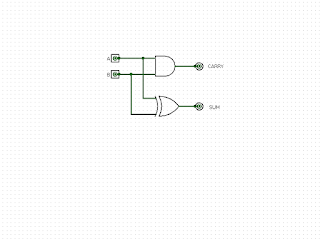
The full adder circuit
The full adder. This is the first full circuit that will go into our home-brewed processor and is in the Arithmetic and Logic Unit (ALU). It is a mix of the previous circuits explained in previous articles and builds on the half adder circuit in the most recent article. This circuit comprises 2 XOR gates, 2 AND gates and a single OR gate as shown in the diagram below, and adds a single bit. Adding just single bits isn't of much utility on it's own, but this circuit gets repeated with the carry out (c-out) of one connected to the carry in (c-in) of the next up to however many bits are required. Inputs A and B are as you'd expect from previous circuits and the c-in is connected to the previous stage as mentioned. How it works I've labelled each of the gates with a number to help with the explanation. You can refer to the truth tables on previous circuits if required as I go through the circuit. With A, B and c-in all at a logic 0 (FALSE), the circuit outputs 0 on both the